Assembly guide of the PlanktoScope
Step 0: Laser cutting
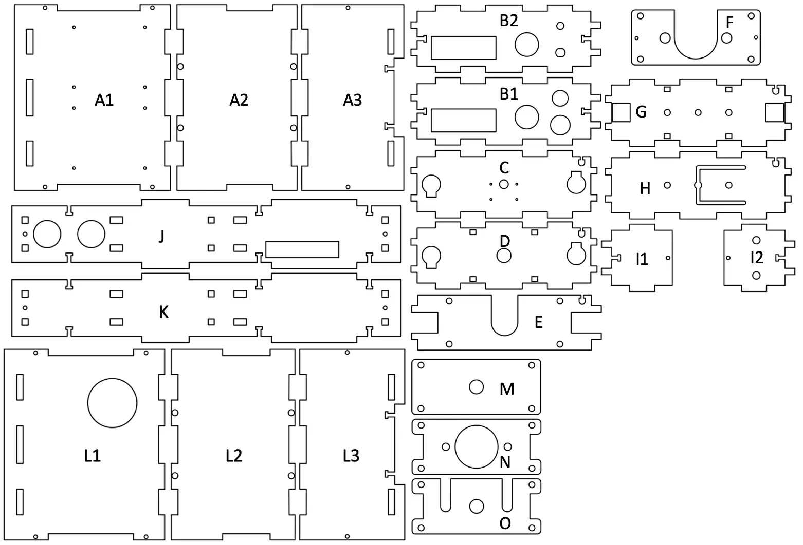
First, you need to make all the laser cuts to have all the necessary plexiglass parts, these cuts are made in opaque and transparent plexiglass of 5 mm, 2 mm and 3 mm. You can download the different plans in .svg format by clicking here. Make sure all holes are completed, and negative space is clear.
Gather all these pieces on a flat surface and make sure you have all the pieces you need to build the PlanktoScope.
You can download them with the following links :
Warning
If you are doing the laser cutting yourself, please take the time to check the calibration of the machine and its power output for the material you are using. A tight fit is needed between the different plates to avoid unwanted spaces between critical parts.
Warning
Depending on the reference of your pump the plans may not be adapted despite the efforts made to have universal plans.
Step 1: Gather everything you need
Next, gather all the components needed to build your PlanktoScope by referring to the following list:
Electonics:
- Raspberry Pi 4
- Motor HAT (this module controls 3 steppers: 2 for thr focus, 1 for the pump)
- GPS HAT
- Fan HAT
- GPIO ribbon connector
- DC Power Jack Socket
- GPS antenna + uFL to SMA adapter (female-female)
- Stepper Motor Peristaltic Pump
- SD card + Adapter (in order to flash the OS image)
Fluidics:
- Tanks
- Silicone tubing ID 1.6 mm
Optics:
- White LED 5 mm
- M12 lens 25 mm
- Other M12 lenses
- Camera Pi V2.1 + flex cable
Other material:
- Standoff assortment kit (M2.5), M2x8mm and M3x12mm screws, M3 nuts
- magnets
Make sure you have your screwdriver kit, soldering iron, and components ready. Also, remember to flash the PlanktoScope image disk on the SD card before installing the Raspberry Pi.
If you are not familiar with any process, such as soldering, tapping, or wiring, try and familiarize yourself with the topics first.
Soldering deals with high heat and potentially toxic materials, so make sure to use the proper precautions.
Step 2: Lenses tapping and mounting
Before starting the assembly and mounting of the different components we will first prepare and mount some parts such as first prepare and mount some parts such as lenses.
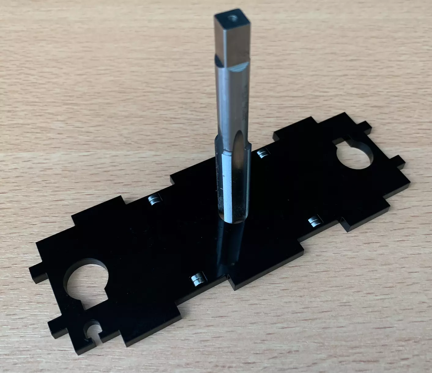
You now need to tap the holes for the M12 lenses in stage and mount it the different M pieces. We must also tap the part D located just after the camera. It is helpful for alignment to do both the objective and tube lens mount together. It is important to do this as straight as possible. A drop of mineral or olive oil can help the process. Be careful to use a right-hand tap (that goes down when turning clockwise).
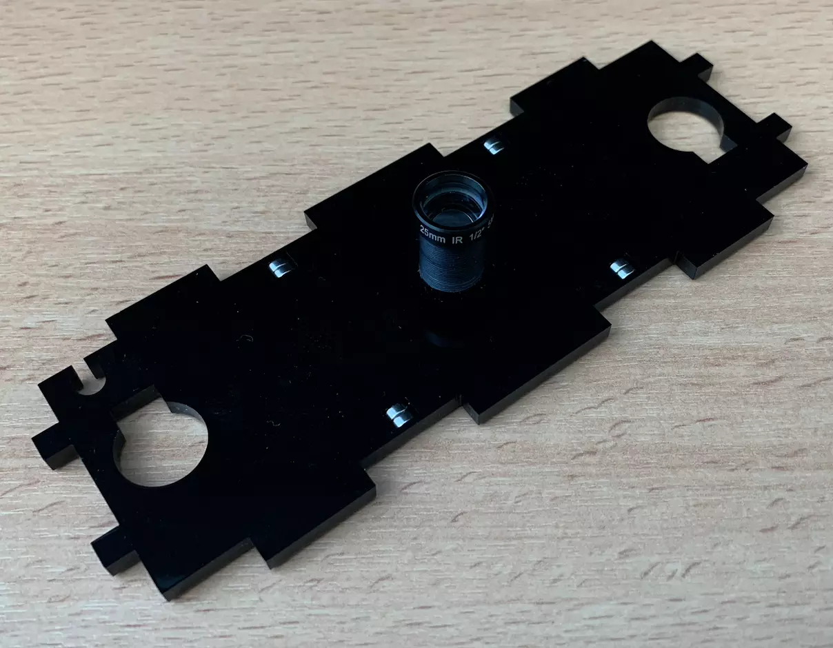
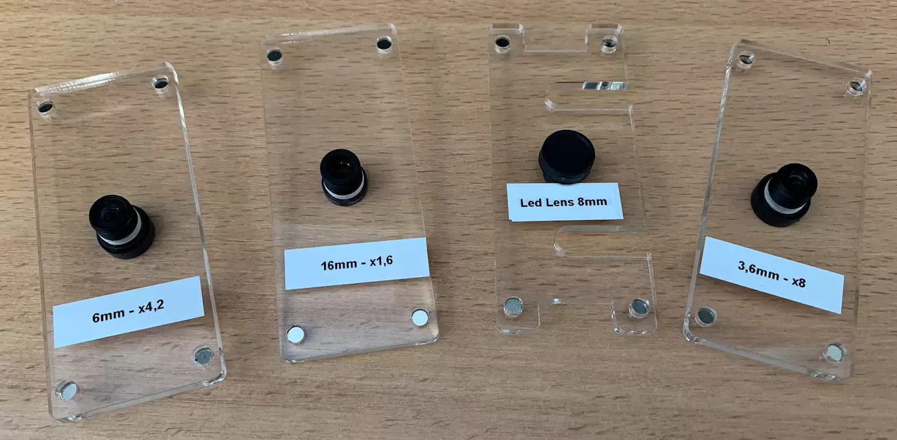
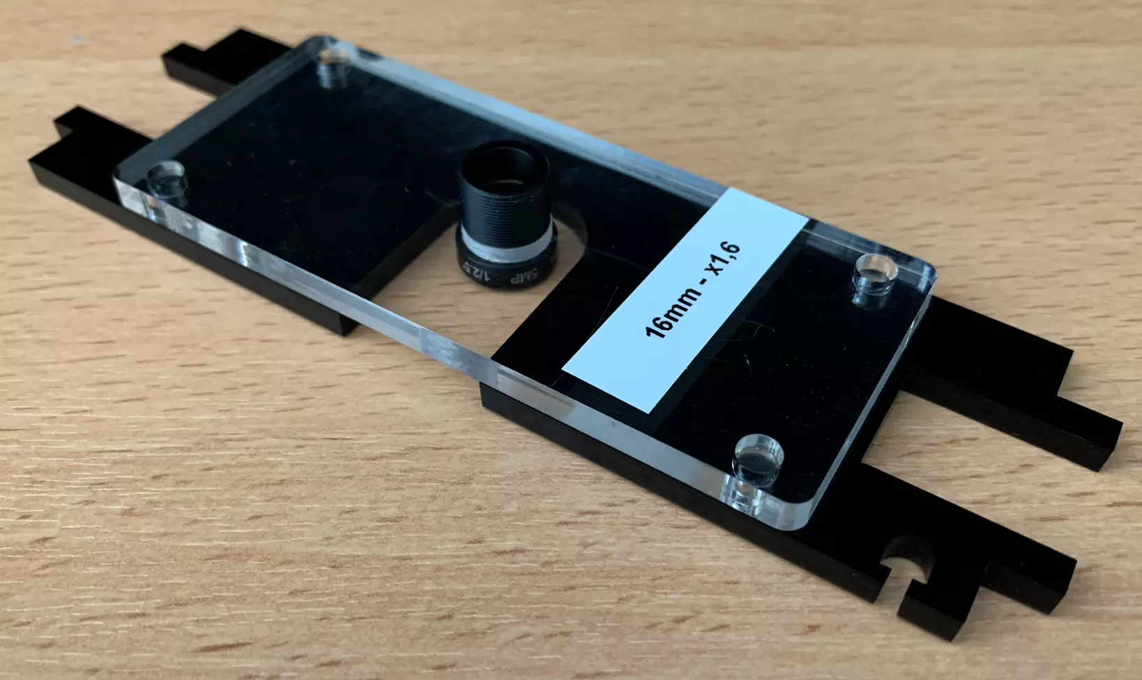
You should get the following set of parts with lenses knowing that this can change depending on the number of lenses you have for the part K.
Step 3: Magnets setup
Now is a good time to think about how the magnets will function within the microscope. The magnets on the sample stage will need to be attracted to the magnets on the flow cell holder. The magnets in the objective holder will need to be attracted the magnets on the mount. Keep this in mind as you are adding your magnets and tapping your respective M12 holders so your orientation will be correct.
To summarize the set of magnets to be placed, there are magnets between:
- Part D and part A2,
- Part G and part A2,
- The part D and the part L2,
- Part G and part L2,
- The part E and the parts containing the different lenses M
The magnets in parts D, G, A2 and L2 must be placed in such a way that the plates fit together as shown in the picture below.
The magnets in parts E and M must be placed in such a way that the plates fit together as shown in the picture below.
The same operation can be repeated on the different plates M containing the lenses.
You can now fix your magnets into their appropriate holes. It is recommended to glue the magnets in place. If the magnets are too large to fit in, the holes can be widened with a handheld drill. However, they should be quite snug in place. Before you glue them in place make sure that the polarity is maintained, as they will be impossible to remove after gluing.
Step 4: Standoff installation
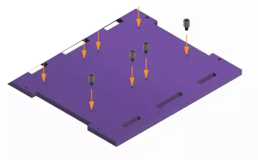
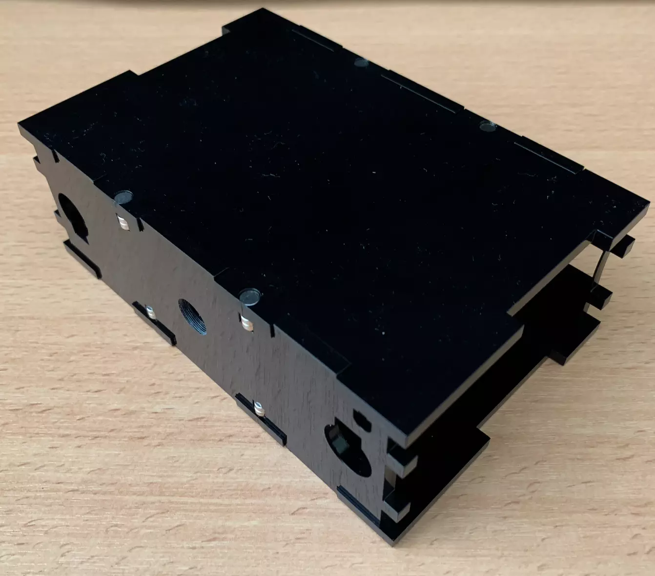
Place 8 standoffs (M2.5 6mm) into the designated holes on the laser-cut base A1. A pair of pliers make the job more comfortable. Do not overtighten as it is possible to crack the base material.

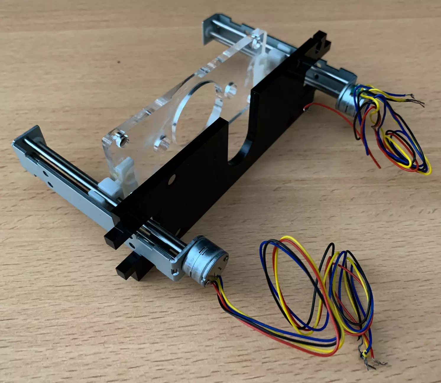
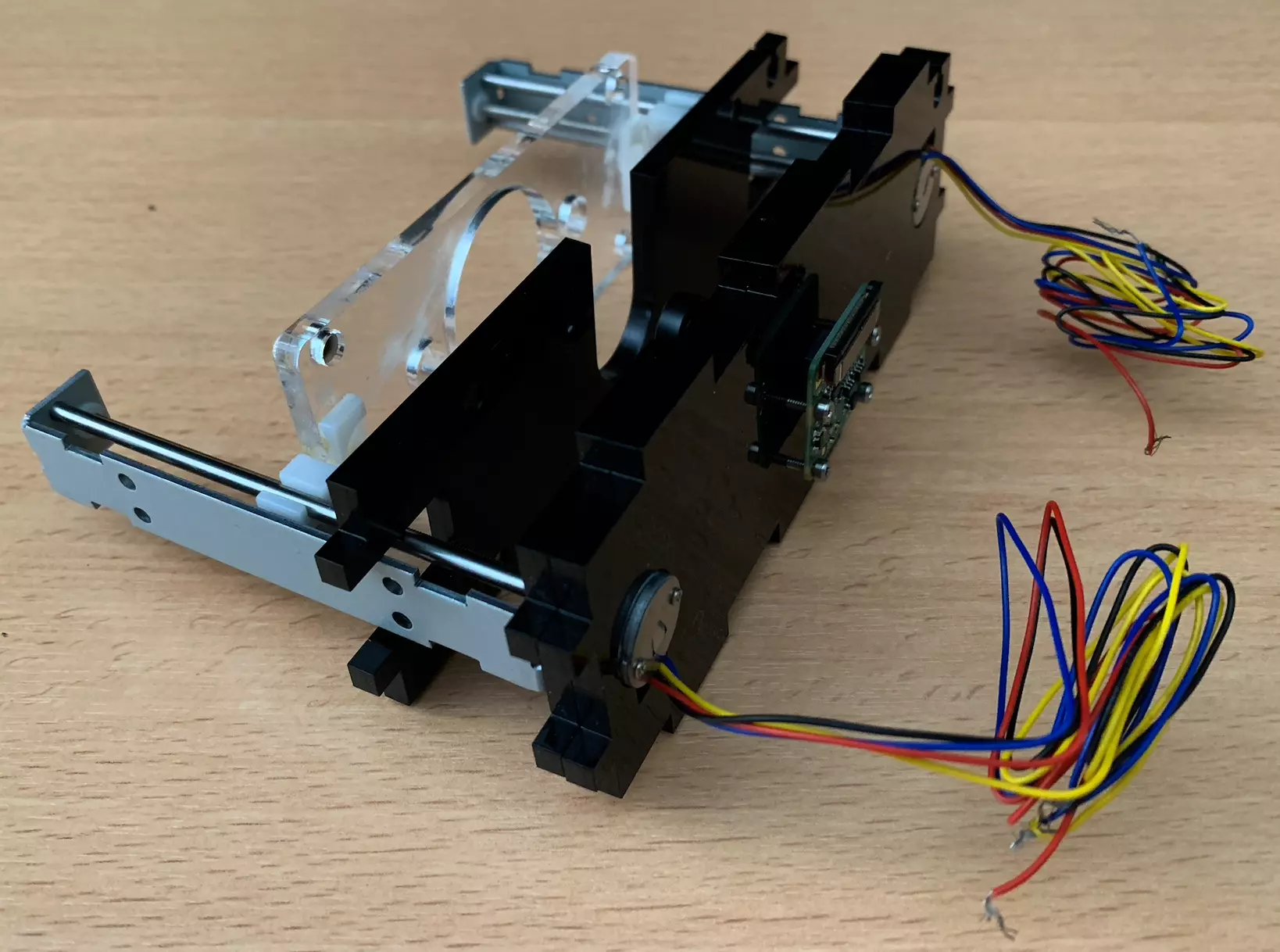
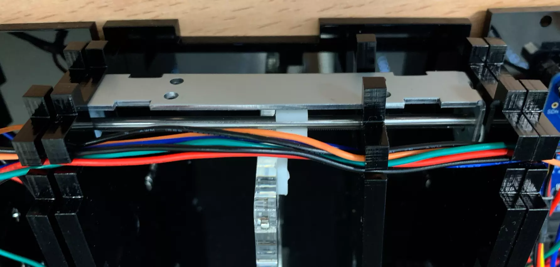
Step 5: Sample stage assembly
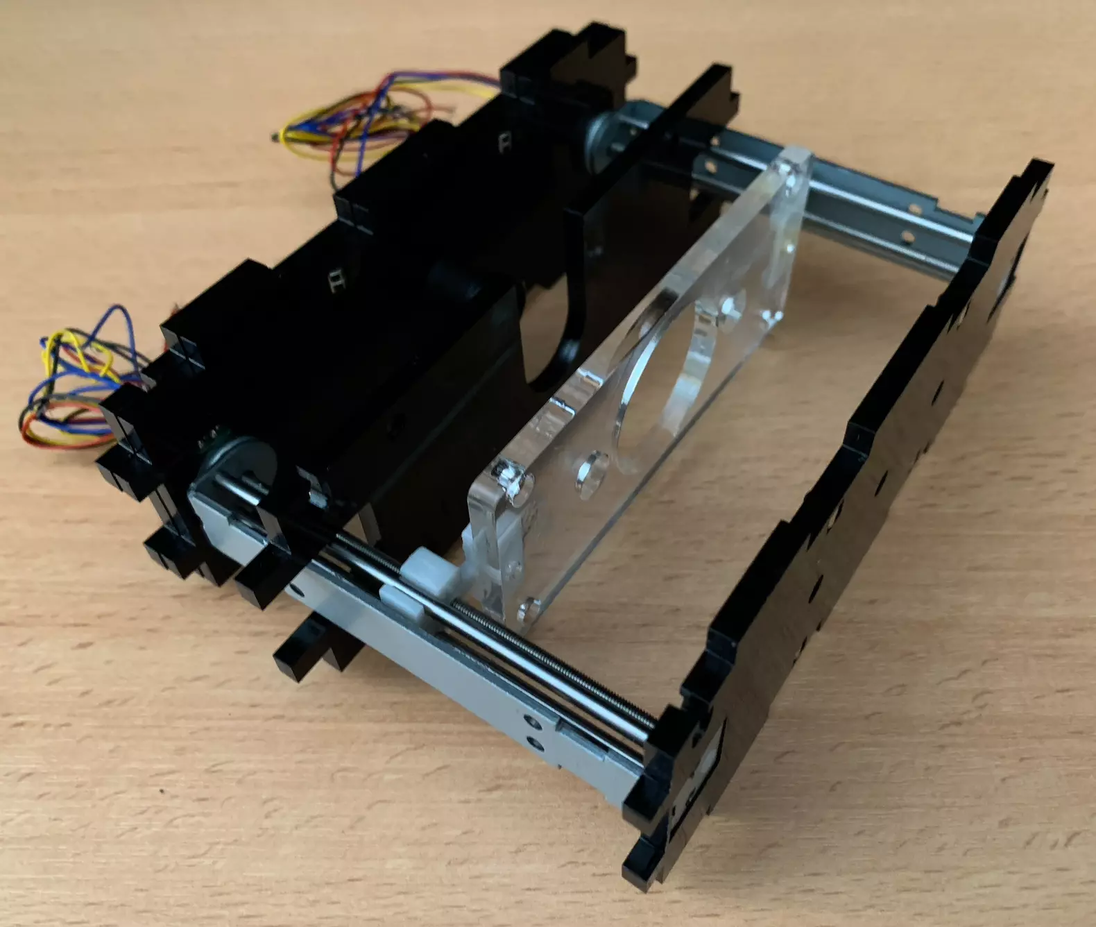
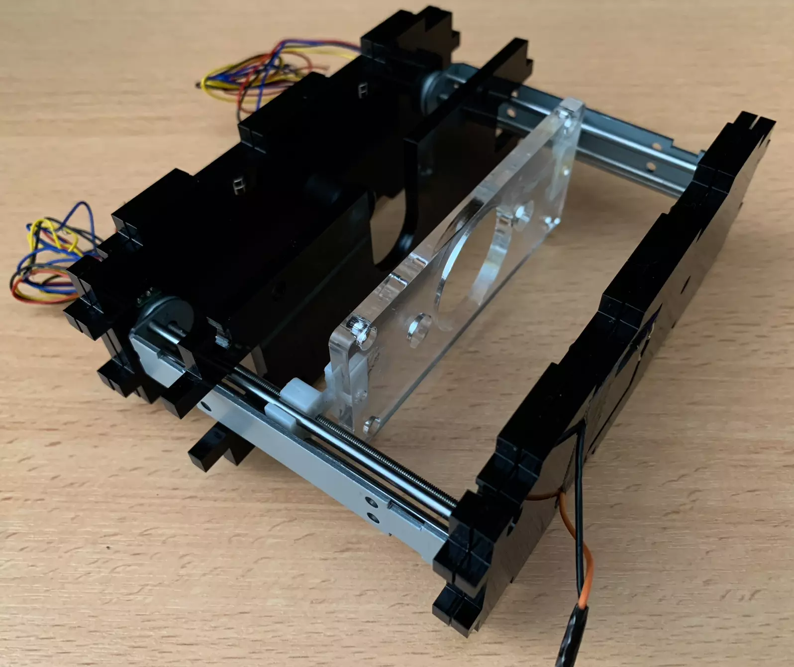
You can now fit the pegs on the driver mounts into the corresponding holes on the sample stage. They should be glued in place with superglue or epoxy. You can spin the shaft to align the driver mounts on the 2 steppers if it helps making the process easier.
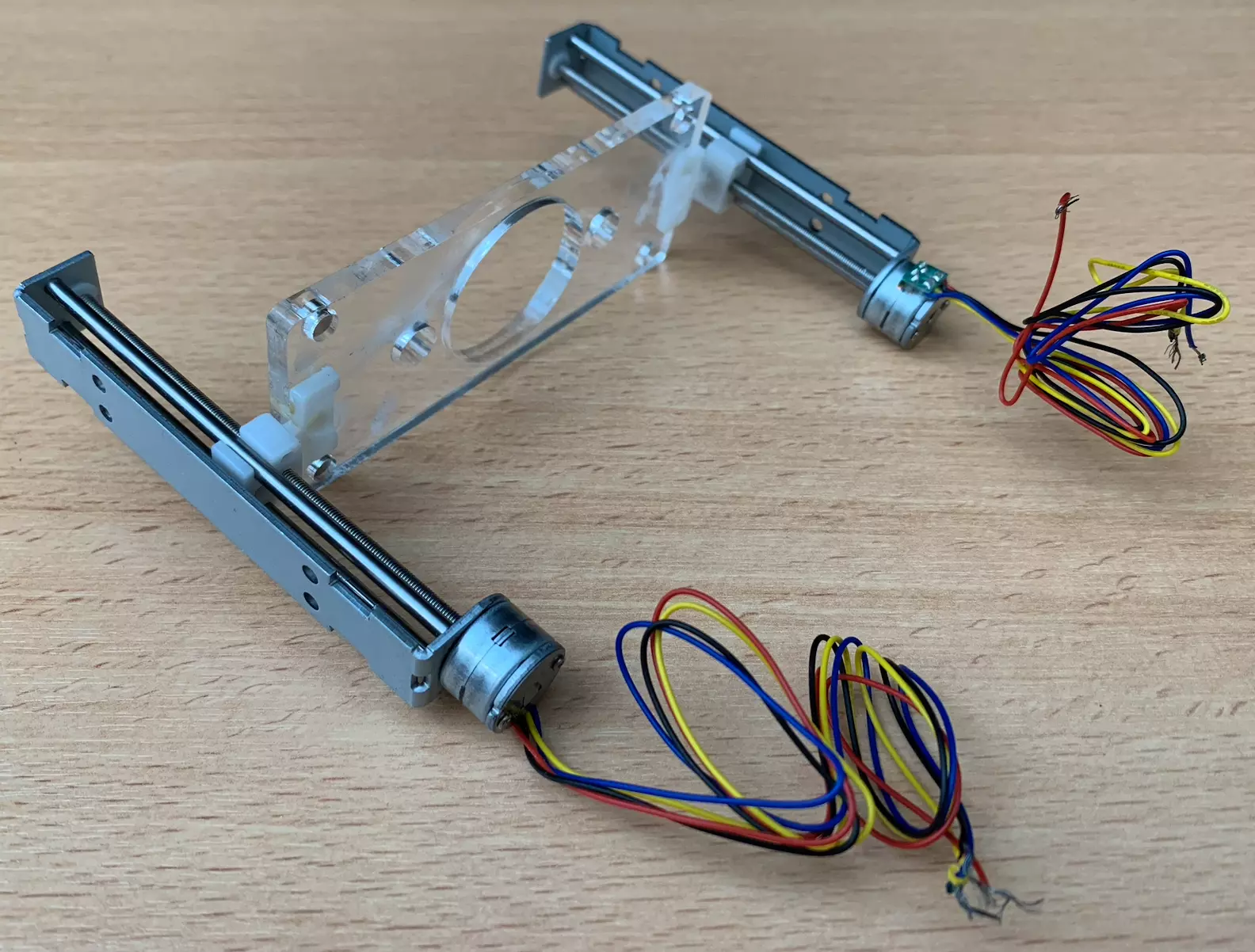
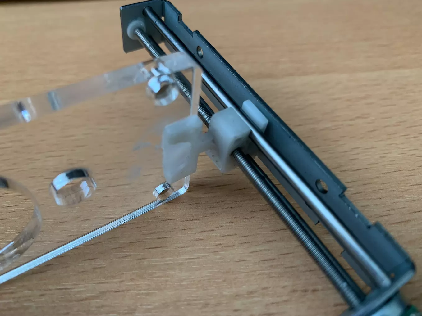
You should now have a sample stage and motor assembly that looks like this.
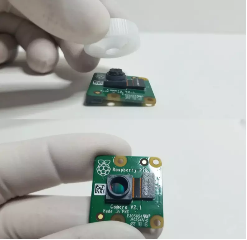
Step 5: Camera preparation
You can now unscrew the lens from the Pi camera, being careful not to disturb the sensor below.
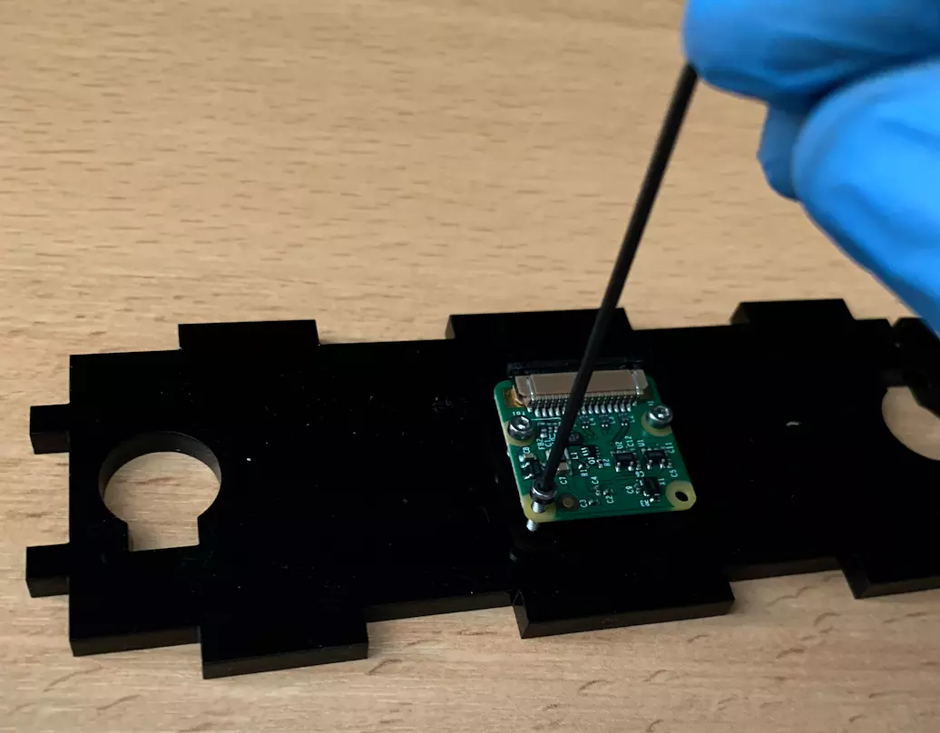
Step 6: Camera mount
You can mount the camera using the appropriate holes on the camera mount C. Be careful to avoid getting oil or dust on the sensor.
Step 7: LED preparation
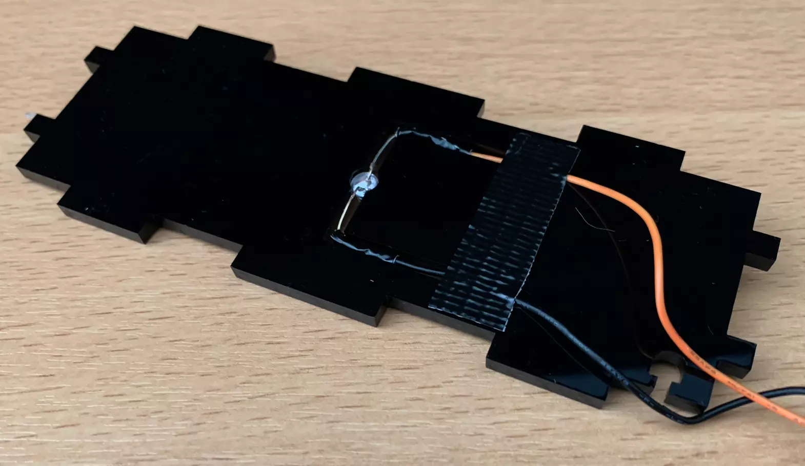
The LED can then be wired up and put into its mount H. If you wire the LED yourself, remember to give enough length to reach the motor driver on the other end of the microscope. You can also add a bit of glue to fix H to the motor mount G at this time to make assembly easier, though it is not required.
Warning
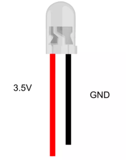
This picture shows the correct wiring for the LED. Please make sure the red wire is on the long pin of the LED.
Step 10: Vertical slices assembly
You can now start placing the motor mount/LED assembly,
- We start by adding the part E,
- Then we add the parts C and D,
- Then the part G,
- And finally the H part.
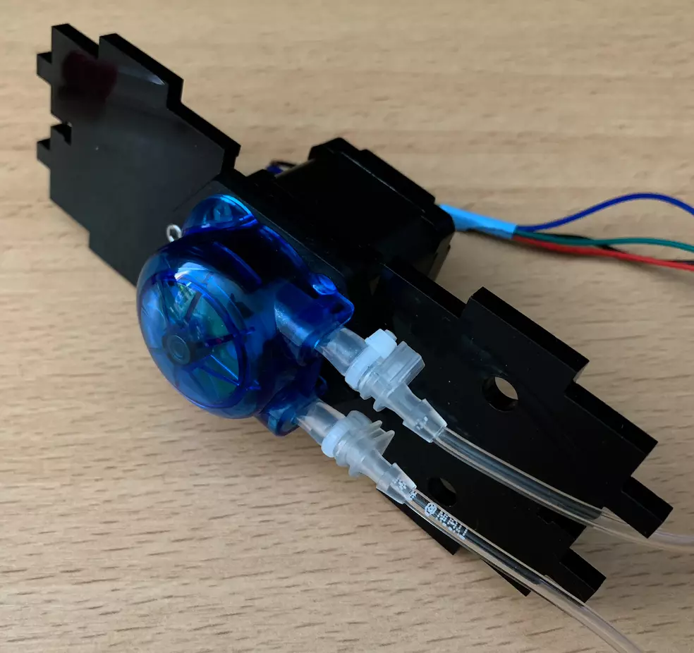
Step 11: Pump setup
The pump can then be mounted in place on I1 and I2. Pass the wires through the hole with the pump tubing pointed toward the holes on the mount. Then fix the pump in place.
Step 12: Connectors
Now we’ll move on to fixing the various connectors of our Planktoscope, i.e. the power supply and the GPS, which are connected to the outside of the PlanktoScope. To do it, we take the parts B1 and B2 and the connectors below.
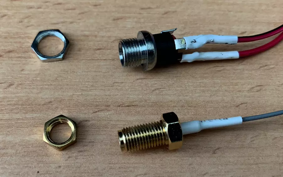
For the power supply we have soldered the + and - as above. We now fix them on the part B2 by passing them through then by tightening them by paying attention to the direction of the plate so that they are directed towards outside. The result is as follows.
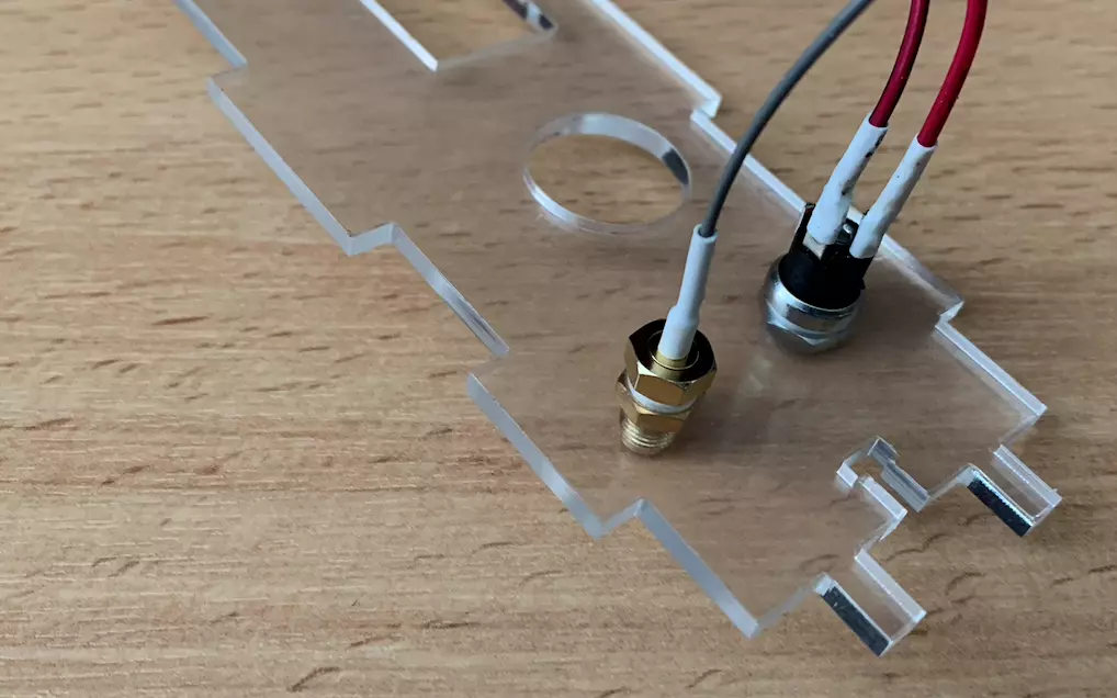
You can if you want glue the B1 and B2 together keeping them well aligned but it is not mandatory.
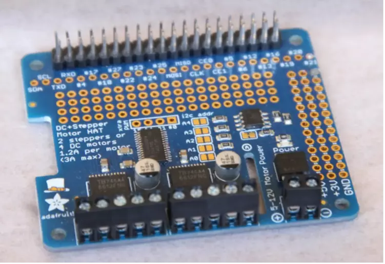
Step 13: Motor HAT wiring
First, insert and solder the terminal blocks and headers onto the motor driver PCB.
Now that once all the components are connected to the motor board and the board itself is ready, we will carry out all the wiring. To do this we will follow the diagram below.
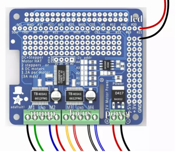
Info
The PlanktoScope uses only bipolar stepper motors (with 4 wires coming out, and two coils inside), so you need to identify the two wires working together for each coil. The RepRap Wiki has great information on how to do this, either with a multimeter or without.
You can find more information about stepper motors and how they work in this document.
Tip
If your wires are too short, you can invert the pump and the focus wiring. However, you will have to remember to change the configuration later on.
Tip
Make sure the wires are properly connected by pulling on them a little. They should not come loose.
To facilitate the organization of the cables in your PlanktoScope, don’t hesitate to use tape or other material to hold them together and prevent them from being disordered
After all the wiring is done, you can attach the board to the A1 part as shown in the image below.
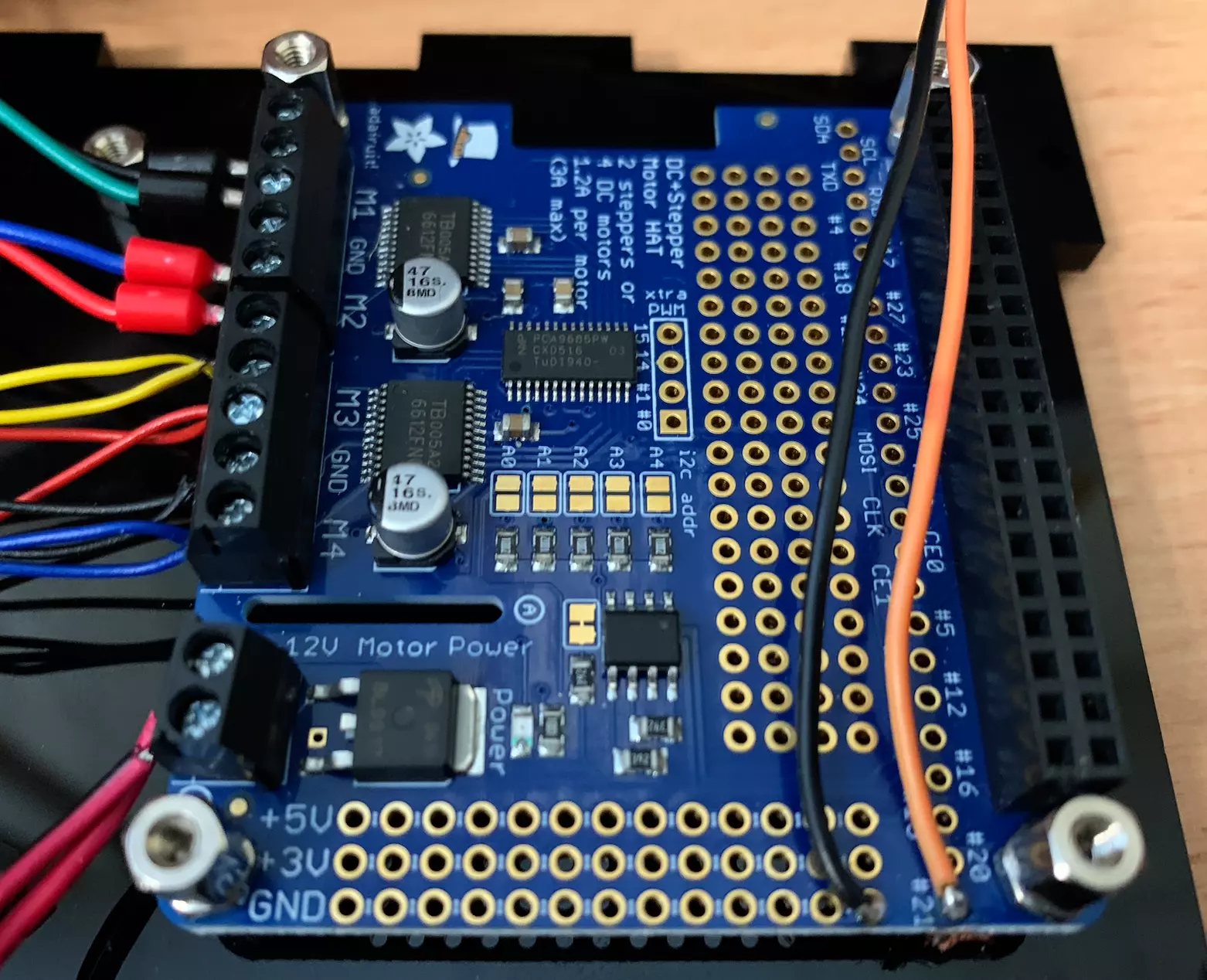
To fix it we will place directly 6mm standoffs with a nut.
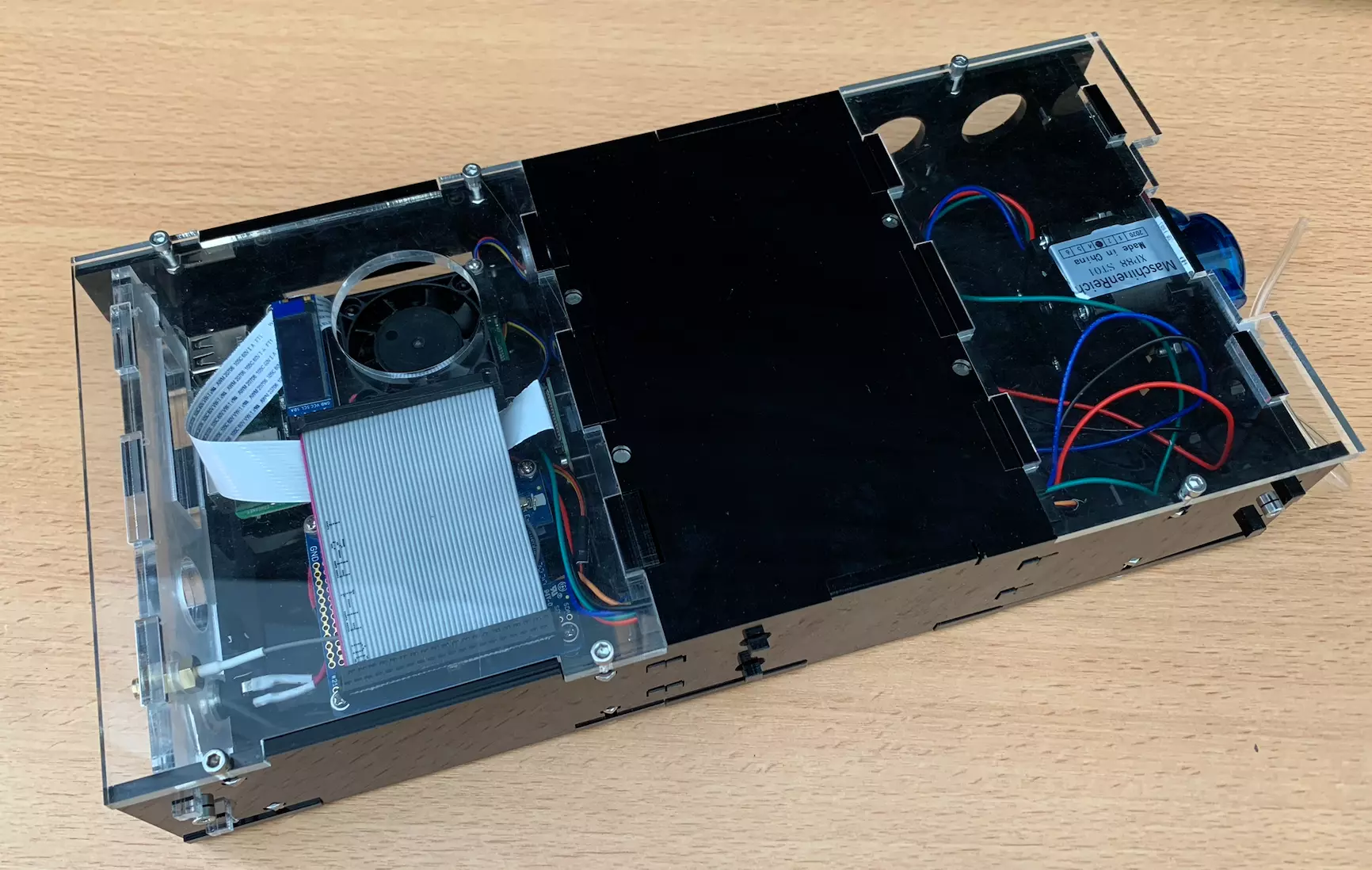
Step 14: Assemblage
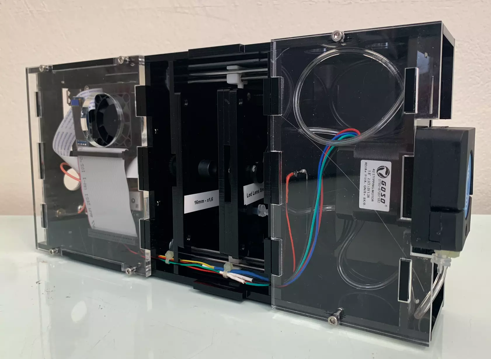
We can now place the different parts that we have made (LED/motor/camera, pump, connectors) on the three parts A1, A2 and A3 taking care to fit the different parts together. For the moment we won’t fix the parts A1, A2 and A3 to the rest, we will do that at the end. Our PlanktoScope is starting to look nice.
Now that everything is in place you can move the different cables in the holes provided on parts C, D, E, F and G as below.
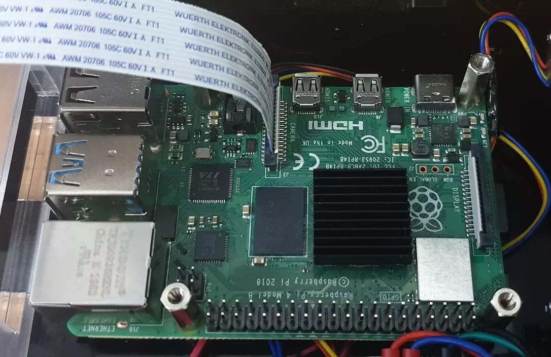
Step 15: Raspberry Pi setup and installation
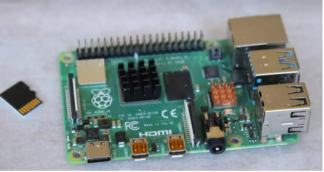
At this point, you can insert your flashed SD card into your Raspberry Pi. Consult the guide for flashing your SD card before you do this. The heat sink can also be added to the processor.
Note
If you choose the Expert path, you still need to flash your sd card, either with the lite version of Raspberry OS or with the desktop version.
Mount the Raspberry Pi containing the flashed SD card on the standoffs attached to the lasercut base A1. You will obtain this:
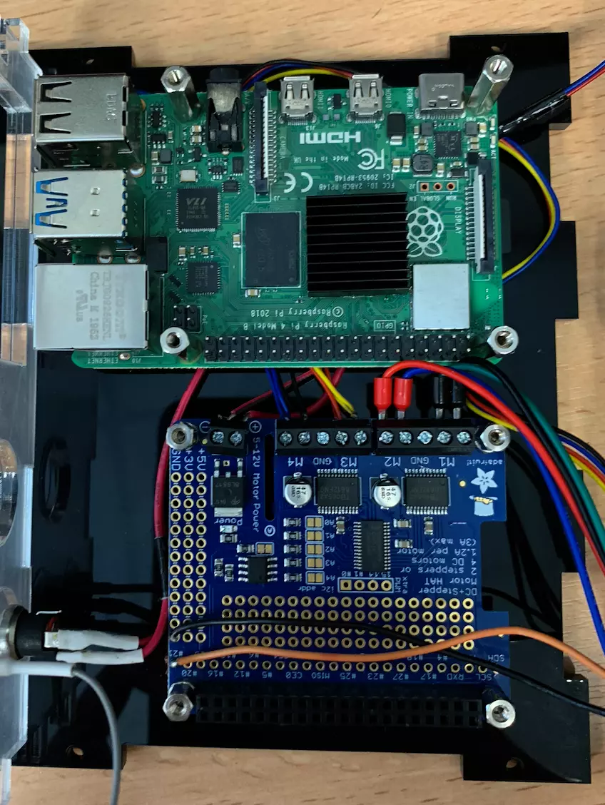
Don’t hesitate to hide the excess cables of the different motors/pumps behind the Raspberry Pi so that it doesn’t interfere with the rest. We fix the Raspberry Pi this time using 10mm standoffs.
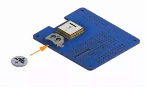
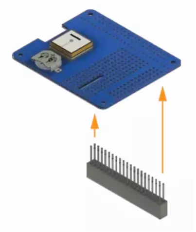
Step 16: Prepare the GPS HAT
Insert the battery to power the GPS HAT and solder the terminal mounts in place.
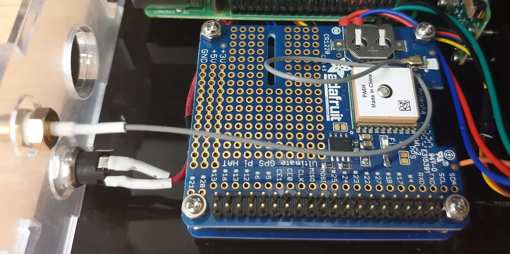
Step 17: Install the GPS HAT
Mount the GPS HAT over the motor driver PCB using the standoffs attached to the laser cut base A1.
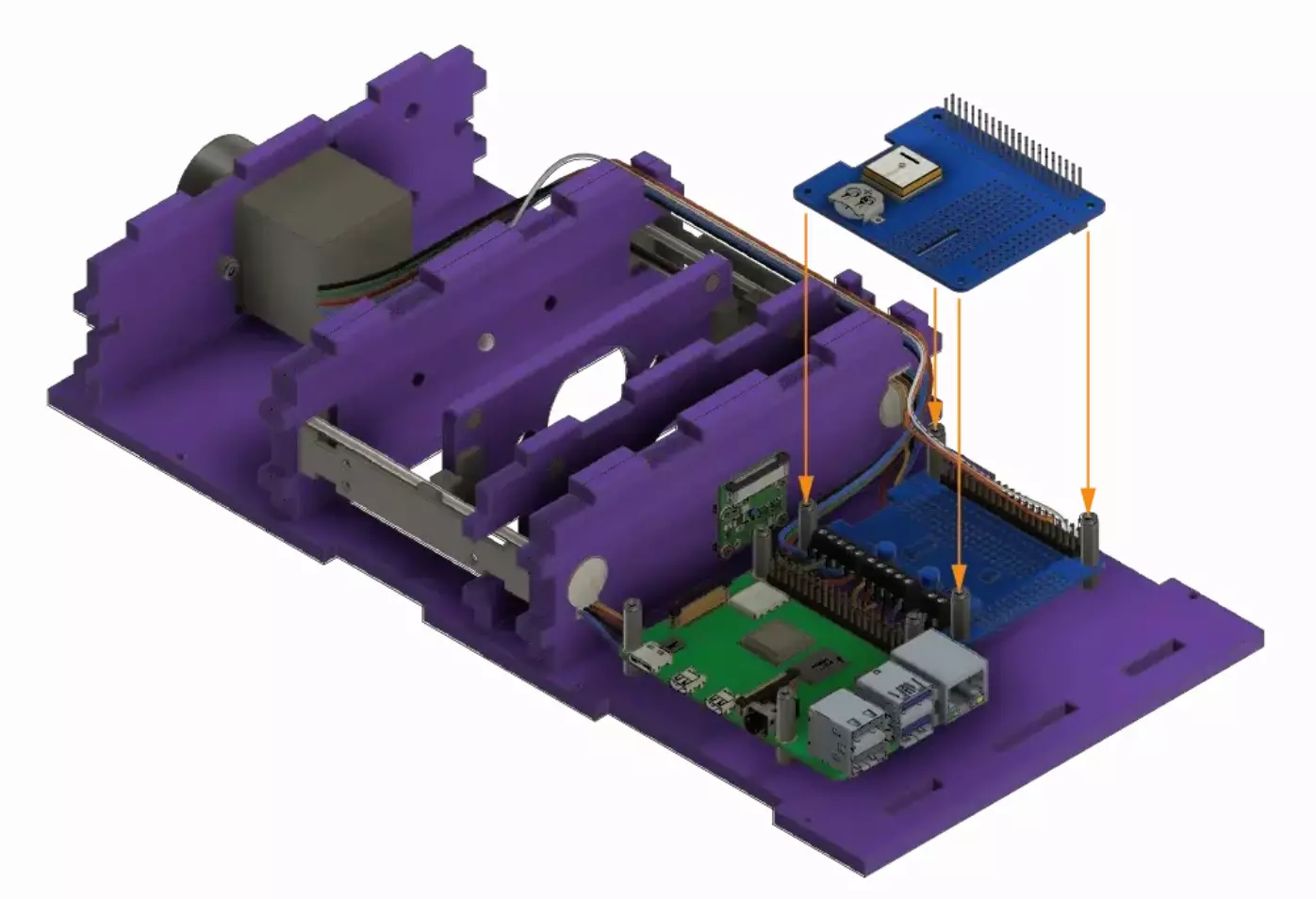
We obtain the following result:
Step 18: Camera flex cable
At this point you can use the Pi’s camera flex cable to connect the camera to the Pi. This is done by gently pulling up the tensioners, inserting the cable in the right orientation, then pushing the tensioners back in place to set the cable. Try not to kink or fold the flex cable too much as it is possible to damage it.
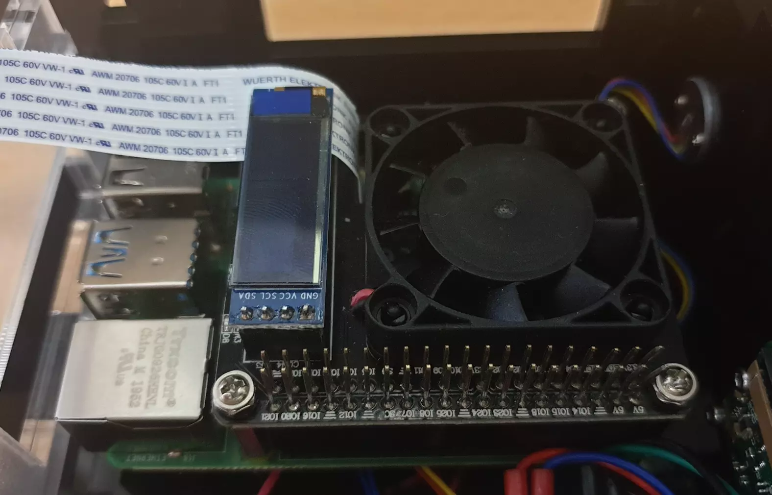
Step 19: Install the Fan HAT
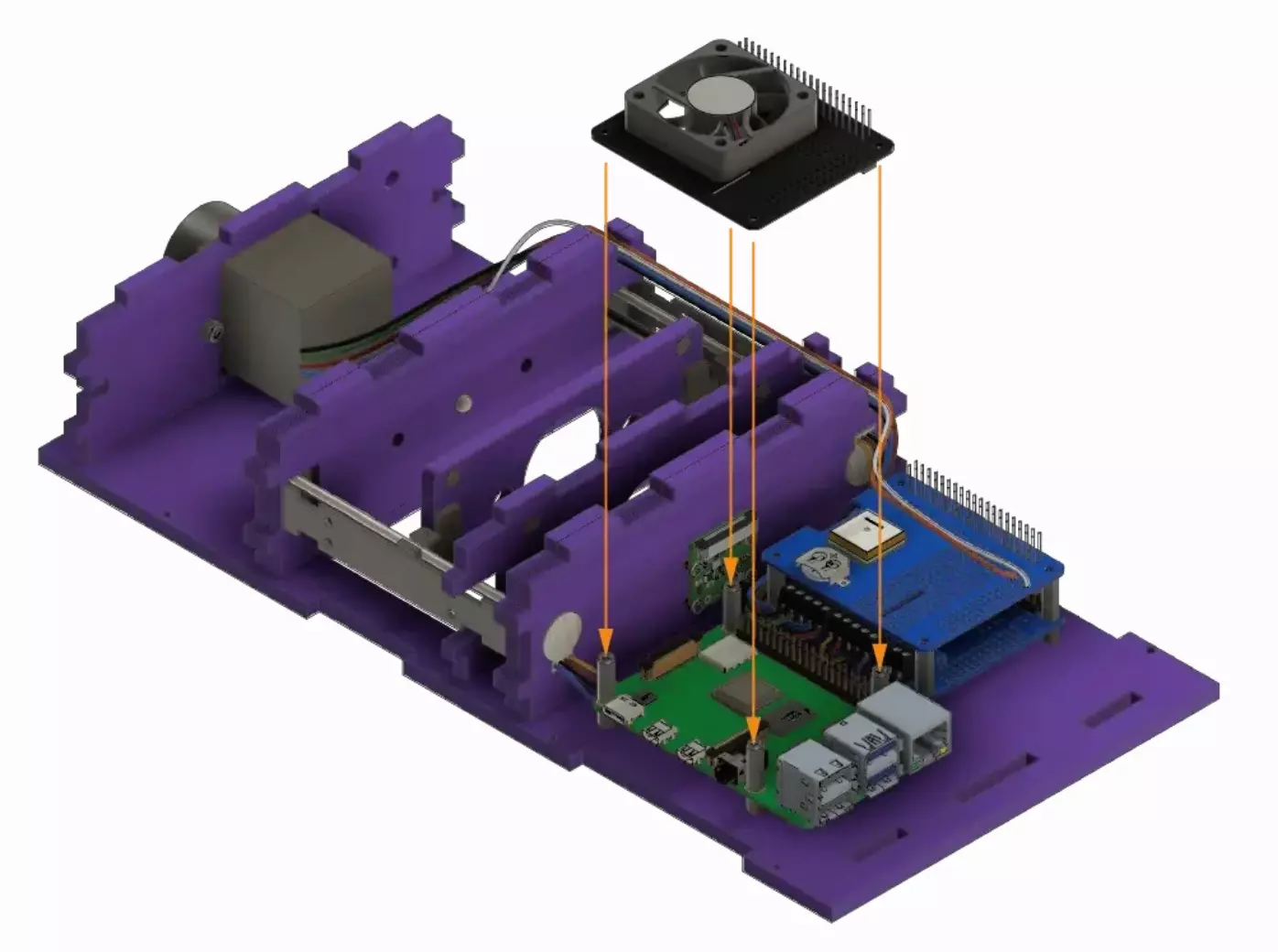
Place the cooling fan HAT above the Raspberry Pi by mounting it to the standoffs on base A1.
Warning
Be careful to slide the camera flat cable in the slot in the HAT above the connector.
We obtain the following result:
Step 21: Secure the HATS
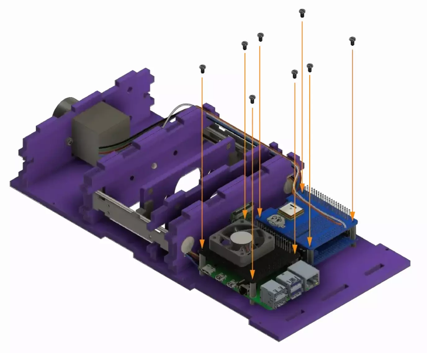
Secure the cooling fan HAT and GPS HAT by tightening the 8 screws to the standoffs on base A1.
Step 22: Insert the camera ribbon cable in the camera
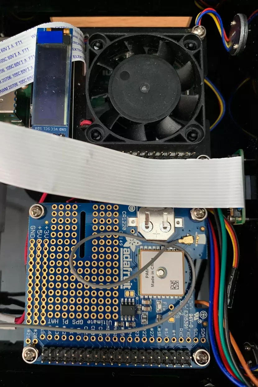
You can now connect the camera flex cable into the connector on the camera board. Once again, gently pull up the tensioners, insert the cable in the right orientation, and push the tensioners back in place to set the cable. Try not to kink or fold the flex cable too much as it is possible to damage it.
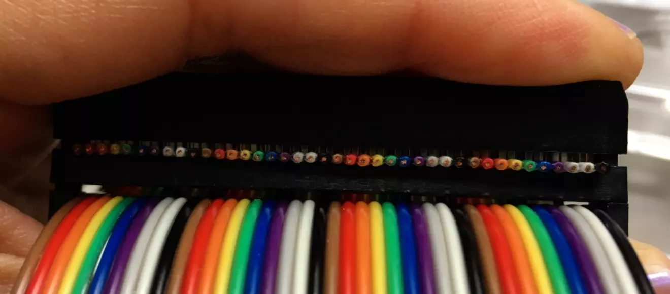
Step 23: Assemble the GPIO ribbon cable
If you didn’t get an already assembled ribbon cable, you need to build it yourself.
The orientation of the connector does not really matter. However, you need to make sure that both connectors are oriented in the same direction and are on the same side of the ribbon.
To assemble, slide the ribbon in its connector and close it off. You need to tighten it really hard. It’s very warmly recommended to use a vice to do so.
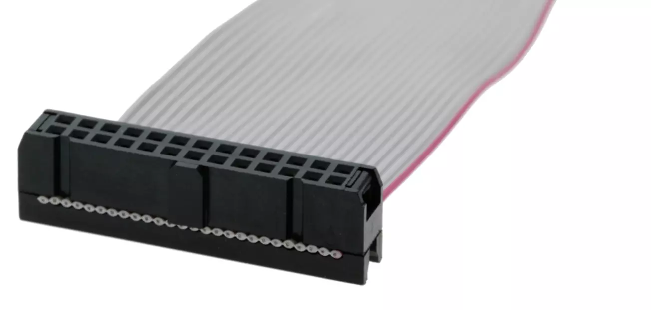
Warning
Once assembled, the ribbon should NOT look like this:
It rather should look like this:
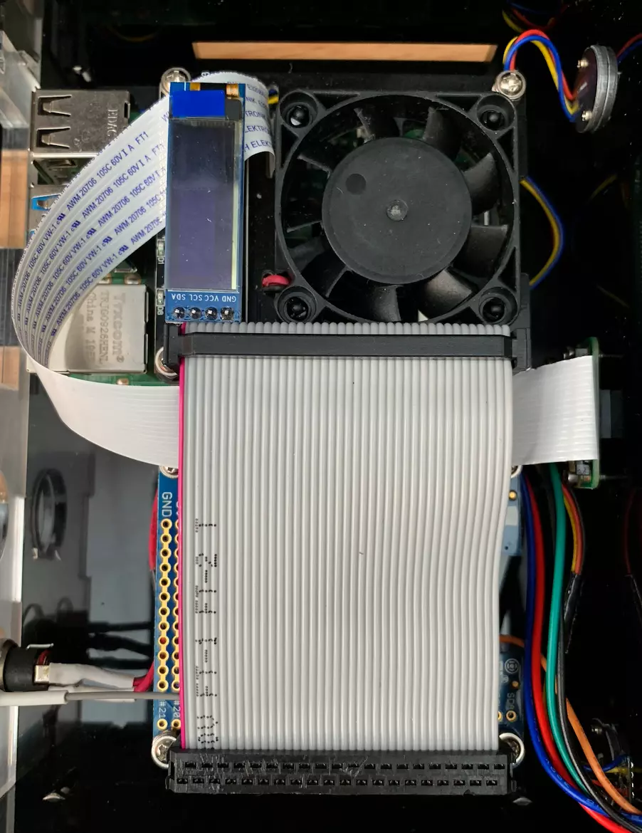
Step 24: Insert the ribbon cable
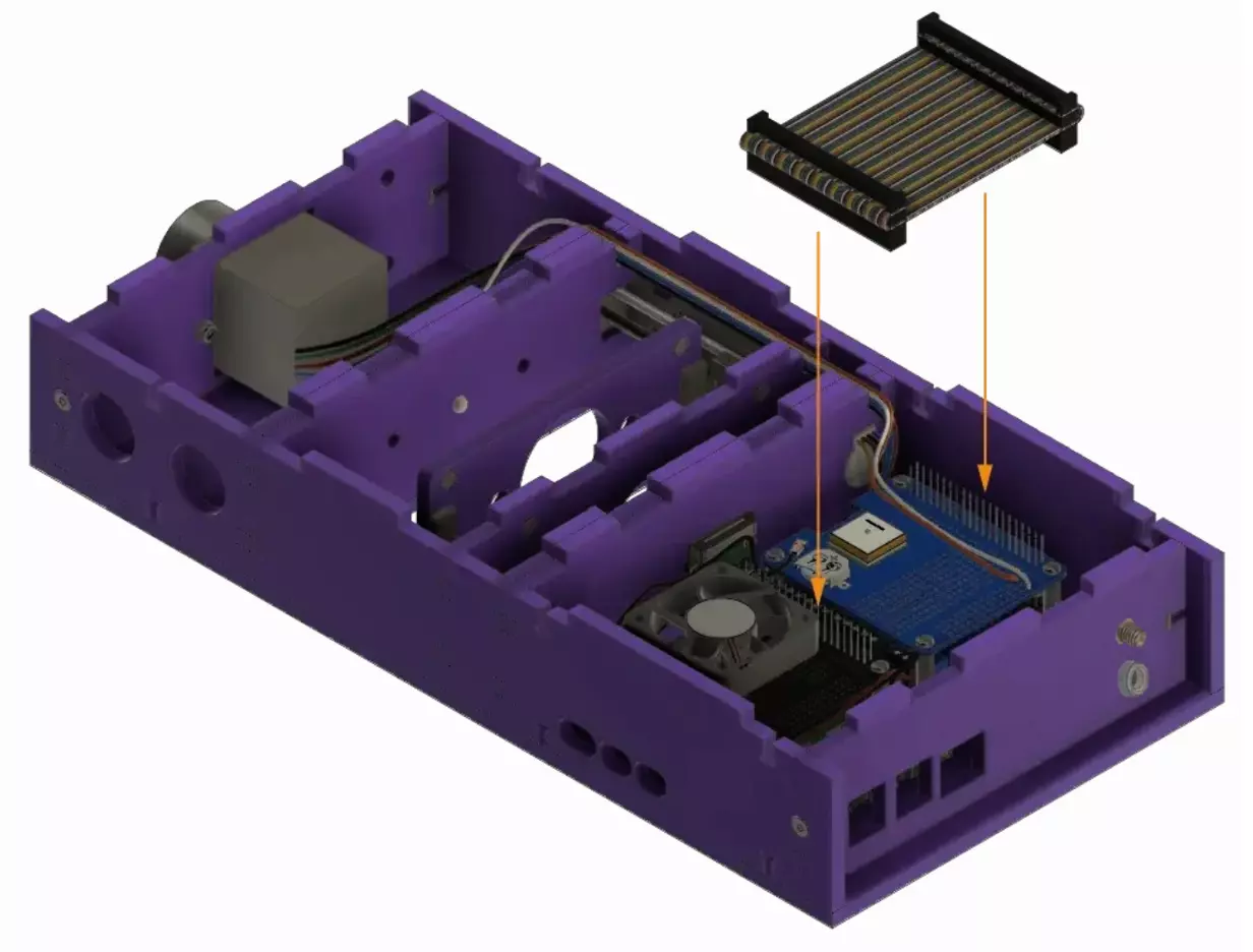
Attach the GPIO ribbon to connect the cooling fan HAT to the GPS HAT.
Tip
You can try to route the flat ribbon from the camera under the ribbon cable you are connecting now.
Step 25: Install side panel
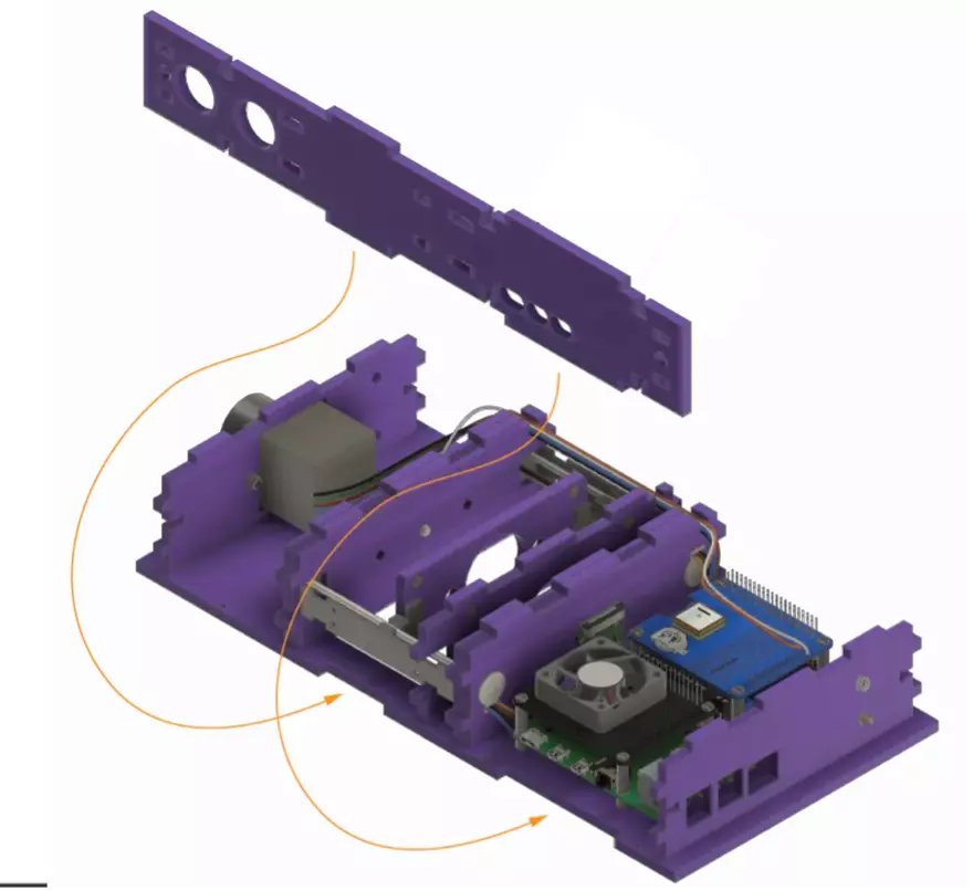
Place the side plate J into the designated slots on the base.
Step 26: Install the other side panel
Mount the side plate K on base A using the assigned slots.
Step 27: Secure the sides together
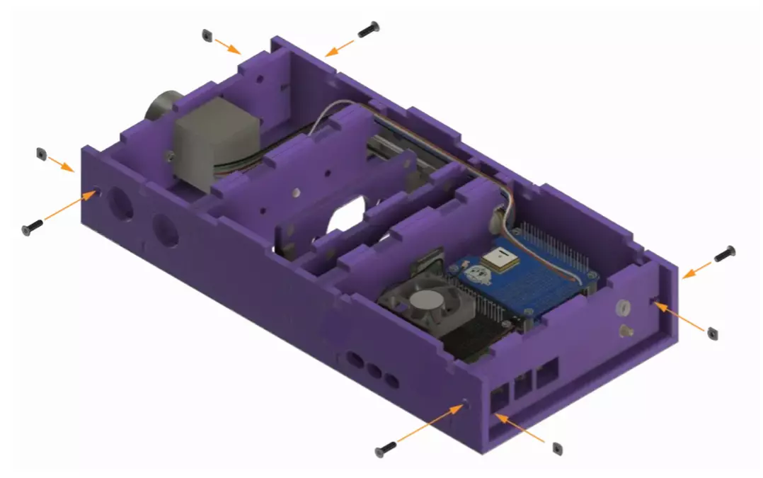
Secure the laser cut sides with the screws and nuts.
Step 28: Secure the sides to the base plate
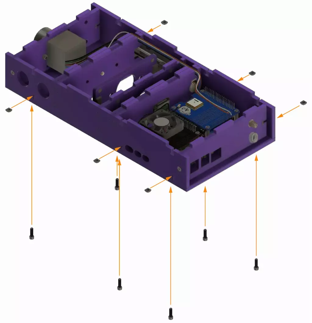
Secure the laser cut sides to the base plate A with the screws and nuts.
Warning
To make this easier, you can turn the assembly upside down or on its side. Be careful when doing so as the plates may fall.
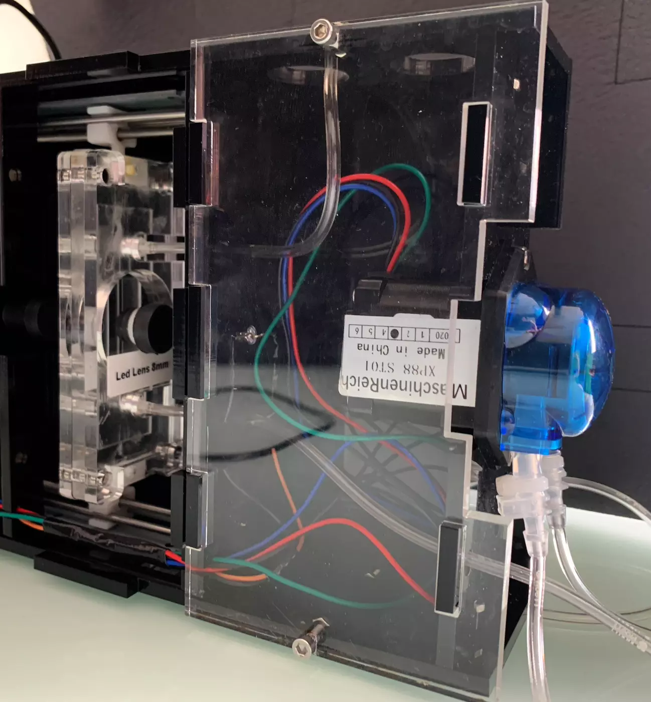
Step 29: Fluidic assembly
Assemble the different pipes so that it looks like the picture below.
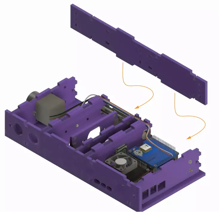
Step 30: Close your PlanktoScope
Warning
Take a moment to check your wiring one last time. Also check the routing, make sure the LED wires and the pump stepper wires are in their dedicated channel.
Place the top L into the slots on the PlanktoScope body. Secure it in place with screws and nuts.
Step 31: Enjoy!
Congratulations on a job well done. You can have some rest, get a tea and some biscuits!
You can now plug the machine and test it. If you have choose the Expert’s path, now it’s a good time to finish setting up your machine.